Technology
Advancements through technology and process improvements have positioned Rocky Mountain Twist as the quality and performance leader of industrial drill bit manufacturing.
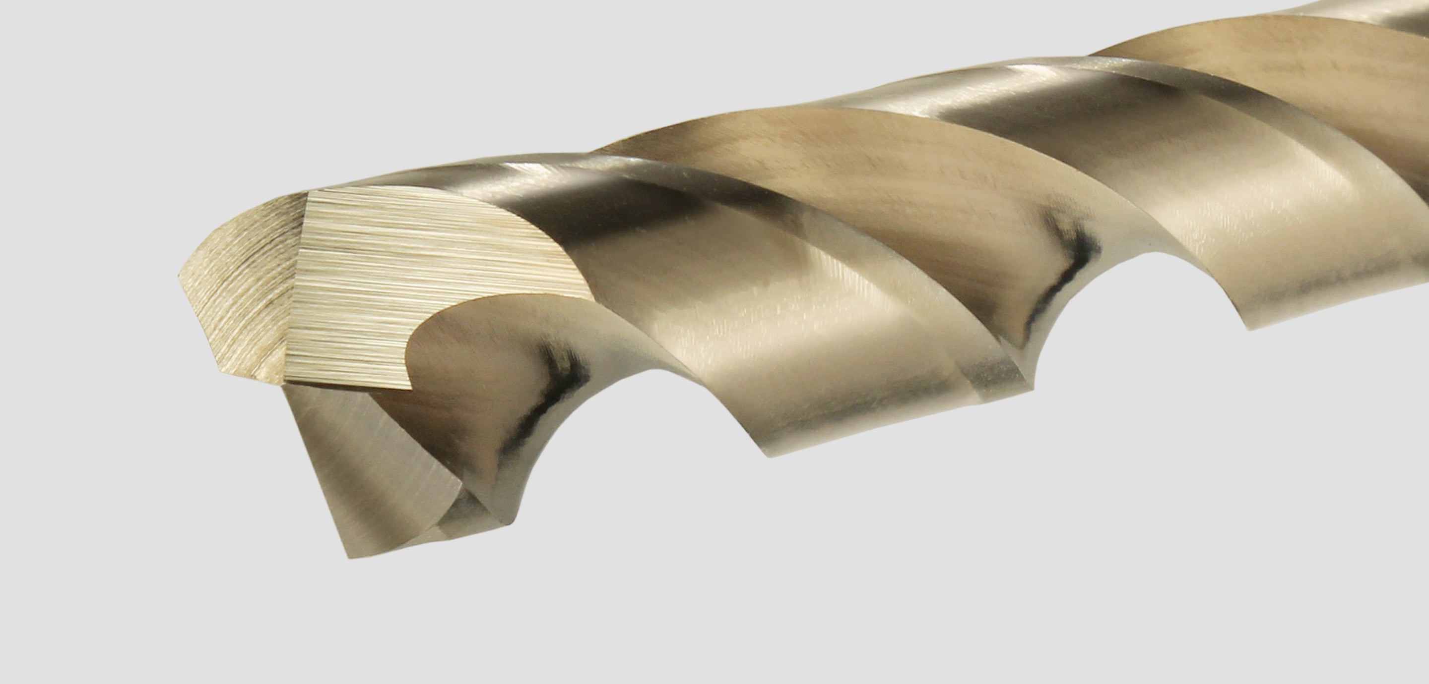
Until recently the process of grinding a drill bit from a solid high-speed steel blank has changed very little over the years. A drill bit produced using traditional manufacturing methods is ground in multiple remote operations within a batch. After each shaping operation the drill bits must be moved "manually" to the next machine or operation. This process is repeated until bits are completely ground. Herein lies the problem, each time a drill bit moves from one operation to the next, the bit is reoriented within a fixture. This constant reorientation can create variances of critical dimensions from one bit to the next. These variations in geometry translate to reduced performance and inconsistencies in hole size.
At RMT, each of our proprietary CNC drill grinding cells transform solid high-speed steel blanks into finished drill bits without leaving the cell or reorientation. Using revolutionary rotary methodology, a drill blank is oriented once, then moves through each manufacturing phase in a precise computer controlled operation. This process innovation ensures the highest degree of repeatable, consistent manufacturing in the industry.
HIGH-TECH QUALITY ASSURANCE
Utilizing the latest advances in optic laser technology, drill bits are continuously measured against predetermined benchmarks. The moment the slightest change in drill geometry is detected, data is received into the cell automatically triggering the grinding wheels to be redressed. This allows RMT technicians to fine-tune the grinding process to meet optimum specifications and eliminate variations in geometry before they happen.
GLOSSARY
(A) TIP DIAMETER
Drill bit diameter at tip
(B) SHANK DIAMETER
Drill bit diameter at shank end
Also includes 3/8" reduction diameter
(C) DRILL LENGTH
Length of drill bit from shank end surface to the leading edge of the primary chisel (measured at the outer diameter)
(D) TIP THICKNESS
Thickness of the web at the point (unless another specific location is indicated)
(E) RELIEVED DIAMETER
Diameter of the drill bit body that has been cut away to minimize friction from the hole
(F) MARGIN WIDTH
Width of the non-relieved portion of the major diameter of the drill bit
(G) CHISEL ANGLE
Included angle between the chisel edge and the leading edge of the cutting lip, as viewed from the front end of the drill
(H) SECONDARY CHISEL ANGLE
Included angle formed by the intersection of the cutting edge and the face of the notch with the relief surface of the point, resulting in partial removal of the primary chisel edge (applies to split point geometry only)
(I) POINT ANGLE
Angle included between the cutting lips projected on a plain parallel to the cutting axis and parallel to the cutting lips
In form this angle resembles a cone, but it departs from a true cone to furnish clearance behind the cutting lips
(J) LIP RELIEF ANGLE
Clearance angle of the cutting lips
Measured by projection onto a plain tangent to the periphery at the outer corner of the lip
The lip relief angle is usually measured across the margins of a twist drill
(K) SECONDARY CLEARANCE ANGLE
Included angle generated from the clearance operation for the secondary cutting edge
(L) FLUTE LENGTH
Length of heliocal flute measured from outer edge of cutting lip to back leadout edge of the flute
(M) CUTTING LENGTH
Length of relieved diameter measured from outer edge of cutting lip to back lead out edge of the relieved diameter grind
(N) WEB
Central portion of the body that joins the lands
Extreme end of the web forms the chisel edge on a two flute drill bit
(O) LAND WIDTH
Peripheral portion of the body between adjacent flutes
(P) RADIUS IN NOTCH
Clearance angle of the cutting lips
Measured by faster, more efficient chip removal